Fórum témák
» Több friss téma |
Fórum » Propeller Clock
Speaking about the zener, the one that is connected in parallel with the 1000µF (the rotor) electrolytic capacitor is a 1N5158?
An 1N5353, 1N5930B would be better. 1N5158 is a trigger diode not a Zener.
Two more things: The photo-transistor in Dario D's pcb is wrong placed? If you look here:
http://www.hobbielektronika.hu/cikkek/files/vicsys_propellerclock/m...ok.lay then you look here (ad file n°1), you can note this. Last one is on the controller that is proposed (ad file n°2), the transistor is a PNP one, but it's value is "BC639" which is a NPN one (see http://alltransistors.com/pdfview.php?doc=bc635_bc637_bc639.pdf&...torola for details). Which is the proper one? PNP or NPN? (Emitter to GND indicates that is an NPN one, am I wrong?). A hozzászólás módosítva: Jan 9, 2014
On RC5X.jpg Q1 sould be an NPN transistor BC639. Sorry my mistake, going to correct it.
I had the same issue before. I forgot to isolate the mosfet from the heat sink. Try it first and see what happens. If you measure the middle pin of your BUZ11 with the hole above to screw it to the heat sink, then you realize that the Drain is in short with GND...
 A hozzászólás módosítva: Jan 9, 2014
Elég gyenge az angol tudásom. :S De nem melegedett túl mivel egyből került rá hűtés.
My English is weak. : S But not too warmed instantly as it was cooling. http://www.youtube.com/watch?v=W59phxXtCEo
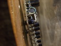
mmmh no. This is not what I meant. What I'm trying to say is that the "metal" from the mosfet haven't touch the heat sink... Look at the picture: Number 1 is the mosfet, that is isolate from the heat sink. Can you see that white washer, before the screw and the grey piece of plastic behind the mosfet? Number 2 is the LM2941, that is not isolated, because GND pin is common with the 7805 and both are commons at the schematics.
A hozzászólás módosítva: Jan 9, 2014
Értelek!
Van alatta szigetelés! Első indításnál észrevettem, hogy nem raktam alá és pótoltam a hiányt. I hear you! There is insulation underneath! First start I noticed that it is not put under and I added the deficit.
Your Issue is on the choice of the regulator, which is basically on the base's design. Instead of an LM317 (that supports only ~1.5A), try with an LM338 (same regulator, but it supports 'till 5A -if I don't remember wrong-). I had a similar experience with another power supply that I made, but I solved by replacing this regulator. I hope it helps to you (tell me about it after try that).
Szia! Ha ment akkor valószínű a bázis hibásodott meg. A zenert azért meg kéne nézni a szekunder oldalon nem e zárlatos a nagy kitöltés miatt el tud az is szállni.. A bázisban a fet szokott meghibásodni vagy megszakad de legtöbb esetben zárlatos lesz. Meg kéne mérni mekkora a feszültség és az áramfelvétel a bázist kiszolgáló tápról. Nem kéne neki 1-1,5A felett lennie. Lehet tekercs zárlat is főleg a primér tekercsen ha bontott esetleg rossz minőségű a huzal miből tekerted,vagy megégett.Ha egy 12V izzót rákötsz a primér tekercs helyére és azt ki be tudod kapcsolni a távirányítóval akkor több mint valószínű a bázis és a fet jó,ha nem akkor a bázsiban keresd a hibát..Ha van szkópod mérj rá megvan e a fet után a PWM.
A hozzászólás módosítva: Jan 9, 2014
Szia!
Nagyon szépen köszönöm a részletes választ. Jelenleg nem vagyok otthon, de mihelyst alkalmam lesz rá átnézem. Két kérdésem lenne (mivel kezdő vagyok). Írtad, hogy zárlatos lehet a zener, azt, hogyan tudom megnézni? Bontott huzalból csináltam, de elsőre működött a prototípus  és azóta újratekertem, de nem lett se jobb, se rosszabb. Szkópom sajnos nincs. és azóta újratekertem, de nem lett se jobb, se rosszabb. Szkópom sajnos nincs. Idézet: „hogy zárlatos lehet a zener, azt, hogyan tudom megnézni” Ellenállásmérővel mindkét polaritásal mérve kicsi ellenállás értéket lehet mérni... Zárlatos...
I think that I found the mistake on Dario's Clock. The GND of the supercap is connected to the pin6 of the pic. This could be the failure. What do you think?
The pcb has a few bugs:
The phototransistor is connected to pin 5 (Vss) and pin 6 (RB0 - INT) of the pic. Correct. The collector of it (flat side) connected to Vss. Not correct, turn it with 180 degree. Pin 6 of pic has a direct connection to goldcap and a connection thrue 100 ohms to +5V. Not correct. Pin6 has to have a 10k pullup to +5V. The Vss in of TSOP1736 has a resistor of 10k instead of 100 ohms. Only concered to supply part of the circuit...
So, I have to exchange the 10KΩ and 100Ω resistors and spin the phototransistor 180 degrees. That's it, right?
A hozzászólás módosítva: Jan 10, 2014
Cut RB0 and the pototransistor's collector form the resistor lower on the picture of board. With a new resistor of 10k pull the RB0 pin and the pototransistor's collector to +5V (the left side of resistor going to pin 2 of TSOP1738). With a new resistor of 100 ohm connect goldcap's + pin to +5V.
Look if I did it right in the schematics (I'll do the same corrections to the board). The red square shows how should be the goldcap connected (if I understood what you answered before).
I did it. Nothing happens: V=5V no changes. R=Infinite no changes.
Done again: with ligth V=4,9V and without light V=5,2V
Any chance to replace the photo-transistor for a photo-led? A hozzászólás módosítva: Jan 11, 2014
This is not good news. When the phototransistor receives light from the IR LED, the voltage approx. 0.8 volts. (L logic level)
It may be too small for the photo transistor pull-up resistance? Increase the 100kOhm on!
I did it. With light: V=5V // Without light: V=4V
Although this error I found the first hour that I have built. The photo transistor is receiving too much light for the room lighting? Try it in the dark the lights switched off. On painted black feathers photo transistor side. Between the transistor and the minimum distance and exact position led to
Ugyan ezt a hibát találtam az első óra amit építettem. A foto tranzisztor túl sok fényt kap a szoba világítása miatt? Próbáld ki sötétben a világítást lekapcsolva. Be festettem foto tranzisztor oldalát fekete tollal. Tranzisztor és a led között minimális távolság és pontos pozició legyen A hozzászólás módosítva: Jan 11, 2014
Is it possible that the phototransistor is connected in reverse polarity?
It seems it was, but since Hp41C said me that I had to turn it 180 degrees, I guess is not. Anyway, I have the same issue on both positions.
A hozzászólás módosítva: Jan 11, 2014
It is possible that broken? You, Probate replace it? (new and already the correct position)
|
Bejelentkezés
Hirdetés |