Fórum témák

» Több friss téma
Fórum » Arduino
A klónok CH340 Soros-USB illesztőjének drivere (Letöltés)
Lapozás: OK   846 / 848
(#) GPeti1977 válasza Jonni hozzászólására (») Júl 27, 2024 /
 
A mikrokontroller tudja azon a lábon fogadni a jelet
(#) Jonni válasza GPeti1977 hozzászólására (») Júl 27, 2024 /
 
Kéne tudja a legtöbb digitális lábon , csak megfelelően kell deklarálni
(#) GPeti1977 válasza Jonni hozzászólására (») Júl 27, 2024 /
 
(#) MATA hozzászólása Aug 4, 2024 /
 
Üdv mesterek!
Van itt ez a kód ez egy akku kapacitásnérő arduino kódja.
A 39-40 sort hibáztatja:
Button BT1(2);
Button BT2(4);
A fordításnál a következő hibaüzenetet írja:
Compilation error: no matching function for call to 'Button::Button(int)'
Mi lehet itt a baj?
Kösszönöm!
  1. /*================================
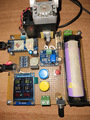
  2. micro:                  Arduino Nano with bootloader Uno    (Arduino Uno)
  3. Display:                TFT ST7789 240x240
  4. Sensor:                 INA219
  5. Power:                 
  6. Data:                   23/01/2023
  7.  
  8. File programma: H:\arduino-1.8.13\portable\sketchbook\Battery_Test_Aldo-v3\Battery_Test_Aldo-v3.ino
  9. Annotazioni:   
  10.  ST7789 240x240 IPS (without CS pin) connections (only 6 wires required):
  11.  #01 GND -> GND
  12.  #02 VCC -> VCC (3.3V only!)
  13.  #03 SCL -> D13                         52 Mega
  14.  #04 SDA -> D11                         51 Mega
  15.  #05 RES -> D9
  16.  #06 DC  -> D8
  17.  #07 BLK -> NC
  18.  
  19.  * Adafruit INA219 Breakout board
  20.  * I2C connections:
  21.  *    SCL pin goes to Nano A5
  22.  *    SDA pin goes to Nano A4
  23.  * VCC to +5V
  24.  * GND to GND
  25.  * Vin- and Vin+ are not used
  26. ===================================*/
  27. #include <Button.h>
  28. #include <Wire.h>
  29. #include <Adafruit_INA219.h>
  30. #include <EEPROM.h>
  31. #include <SPI.h>
  32. //#include <Adafruit_GFX.h>
  33. #include <Arduino_ST7789_Fast.h>
  34.  
  35. // pin I/O Arduino
  36. #define end_sounder  A2 //buzzer
  37. #define potPin  A0                //potenziometro
  38.  
  39. Button BT1(2);
  40. Button BT2(4);
  41.  
  42. // pin display ST7789
  43. #define TFT_DC    8
  44. #define TFT_RST   7
  45. // dimensione schermo display
  46. #define SCR_WD 240
  47. #define SCR_HT 240
  48. // define what kind of fonts should be used
  49. #define USE_RRE_FONTS 1
  50.  
  51. Arduino_ST7789 lcd = Arduino_ST7789(TFT_DC, TFT_RST);
  52.  
  53. #include "RREFont.h"
  54. #include "rre_term_10x16.h"
  55. #include "rre_bold13x20.h"
  56. #include "rre_bold13x20v.h"
  57. #include "rre_bold13x20no.h"
  58.  
  59. RREFont font;
  60. // needed for RREFont library initialization, define your fillRect
  61. void customRect(int x, int y, int w, int h, int c) { return lcd.fillRect(x, y, w, h, c); }  
  62.  
  63. //-----------------------------------------------------------------------------
  64.  
  65. unsigned long ms = 0;
  66. int stato = 10;
  67. boolean FIRST = true;
  68. boolean ONCE = true;
  69.  
  70. int target_mA;                      //= 100;
  71. float cutoff_voltage;           //= 3.2;
  72. float kP;                               //= 50;
  73. float v1,v2,v3;
  74. int a1, a2, a3;
  75. float b1, b2, b3;
  76. byte cifra[4];
  77. char str_h[3];                          //stringa per ore
  78. char str_m[3];                          //stringa per minuti
  79. char str_s[3];                          //stringa per secondi
  80.  
  81.  
  82. //================== variabili per  RUN  ==================
  83. int time_limit = 360;       // 6 hours. Test relies on the..    
  84. float offset = 0.0;
  85. int tolerance = 1;
  86.  
  87. //int pwm = 0;
  88. float error;
  89. boolean manual = false;
  90.  
  91. String SW_VERSION = "3.04";
  92.  
  93. // Current shunt and voltage measurements
  94. Adafruit_INA219 ina219;
  95.  
  96. float shuntvoltage = 0;
  97. float busvoltage = 0;
  98. double current_mA = 0;
  99. float loadvoltage = 0;
  100. float power_mW = 0;
  101. /*
  102.   * La seguente variabile visualizza la tensione della cella.
  103.   * C'è una costante R che può essere impostata nella routine read_INA che può
  104.   * essere utilizzato per tenere conto delle perdite di cablaggio o traccia PCB nel loop di corrente.
  105.   * Se puoi misurarlo.
  106.   * Puoi anche utilizzare un DVM molto accurato per confrontare la tensione della cella
  107.   * con ciò che misuri e modifica questa variabile in modo che corrisponda a quanto visualizzato
  108.   * tensione di cella. Se ci tieni a questa precisione...e cell voltage
  109.  */
  110. float vR;
  111.  
  112. // lapse timer for test duration and mAh calculation
  113. unsigned long  startMillisec;           // Variables for discharge timer.
  114. unsigned long  sampleTime = 10000;      // Default samples to PC time (ms)
  115. unsigned long millis_PC_wait;           // Timer for samples to PC
  116. unsigned long millisCalc_mAh;           // Timer for mAh calc. and LCD write.
  117. float last_hours = 0.0;                 // Working variables for time and mAh
  118. float mAh_soFar = 0.0;
  119.  
  120. int days, hours;
  121. int mins, secs;
  122. int tMins;
  123.  
  124. // Beeper
  125. boolean sounded = false;  // flag to limit beeping
  126. int beep = 1;             // value coming from PC, no longer used
  127.  
  128. // Variables and flags to terminate test
  129. int cancel = 0;
  130. boolean timed_out = false;
  131. boolean high_current = false;
  132. boolean cutoff_voltage_reached = false;
  133. String error_code = "";
  134. boolean end_of_test = false;
  135.  
  136. //------------------------------------------------------------
  137. /* a hack to create up to 16-bit PWM signals:
  138.  * The above one is WRONG! Below is the correct one.
  139.  *
  140.  * I use the 13-bit version because the resolution of the 10-bit counter is too
  141.  * course to drive the error variations.
  142.  */
  143. void setupFastPWM() {
  144.   /* Changing ICR1 will effect the resolution and the frequency.
  145.   ICR1 = 0xffff; (65535) 16-bit resolution  244 Hz
  146.   ICR1 = 0x7fff; (32767) 15-bit resolution  488 Hz
  147.   ICR1 = 0x3fff; (16383) 14-bit resolution  977 Hz
  148.   ICR1 = 0x1fff;  (8192) 13-bit resolution 1953 Hz
  149.   ICR1 = 0x0fff;  (4096) 12-bit resolution 3908 Hz
  150.   */
  151.   DDRB |= (1 << DDB1) | (1 << DDB2);
  152.   TCCR1A = (1 << COM1A1) | (1 << COM1B1) | (1 << WGM11);
  153.   TCCR1B = (1 << WGM12) | (1 << WGM13) | (1 << CS10);
  154.   OCR1A = 0;
  155.   ICR1 = 0x1fff; /* TOP counter value (freeing OCR1A)*/
  156. }
  157. //----------------------------------------------------------
  158.  
  159. /* xx-bit version of analogWrite(). Works only on pins 9 and 10. */
  160. void analogWriteFast(uint8_t pin, uint16_t val)
  161. {
  162.   switch (pin) {
  163.     case  9: OCR1A = val; break;
  164.     case 10: OCR1B = val; break;
  165.   }
  166. }
  167. //--------------------------------------------------------------------
  168.  
  169. // PWM setup
  170. const byte pwm_pin = 9;   // PWM DAC, only pins 9 and 10 are allowed with the fast PWM
  171. int pwm = 2000;           // Starting value for 13-bit DAC. PWM is typ. @ 4540
  172. float pid_error;          // the error between current setiing and actual current,
  173.                           // used in the "PID" calculation to drive the MOSFET
  174. //==========================================================
  175.  
  176. void setup()
  177. {
  178.   Serial.begin(9600);
  179.   lcd.init(SCR_WD, SCR_HT);
  180.   font.init(customRect, SCR_WD, SCR_HT); // custom fillRect function and screen width and height values
  181.  
  182.  
  183. //inizializzazione EEPROM solo prima volta quindi remmare
  184.   //EEPROM.put(0, target_mA);                   //scrivi target_mA
  185.   //EEPROM.put(10, cutoff_voltage);             //scrivi cutoff_voltage
  186.   //EEPROM.put(20, kP);                                 //scrivi kP  
  187.   EEPROM.get(0, target_mA);
  188.   EEPROM.get(10, cutoff_voltage);
  189.   EEPROM.get(20, kP);
  190.  
  191. // Inizializza  INA219.
  192.   // Per impostazione predefinita, l'inizializzazione utilizzerà l'intervallo più ampio (32 V, 2 A). Tuttavia
  193.   // puoi chiamare una funzione setCalibration per modificare questo intervallo (vedi commenti).
  194.   ina219.begin();
  195.    
  196.   BT1.begin();
  197.   BT2.begin();
  198.   pinMode(end_sounder, OUTPUT);       // Output to sounder.
  199.   digitalWrite(end_sounder, LOW);
  200.  
  201. // Set up DAC pin come output
  202.   pinMode(pwm_pin, OUTPUT);
  203.  
  204. }
  205.  
  206. //const uint16_t lnCol  = RGBto565(255,150,255);
  207. const uint16_t ln2Col = RGBto565(180,180,180);          //bianco
  208. const uint16_t labCol = RGBto565(250,250,250);          //grigio
  209. const uint16_t v1Col  = RGBto565(100,250,100);          //verdino
  210. const uint16_t v4Col  = RGBto565(255,0,0);                      //rosso
  211. const uint16_t v2Col  = RGBto565(235, 164, 52);         //arancio
  212. const uint16_t v3Col  = RGBto565(66, 135, 245);         //azzurro
  213. const uint16_t v5Col  = RGBto565(255, 255, 0);          //giallo
  214.  
  215. int mode=0,lastMode=-1;
  216.  
  217. void setBigNumFont()
  218. {
  219.  
  220.   font.setFont(&rre_Bold13x20v);
  221.  
  222.   font.setSpacing(1);
  223.   font.setScale(1,2);
  224.   font.setDigitMinWd(16);
  225. }
  226.  
  227.  
  228. void drawField(int x, int y, int w, int h, char *label, uint16_t col=v3Col)   //disegna i campi
  229. {
  230.   lcd.drawRect(x,y+7,w,h-7,col);
  231.   font.setFont(&rre_term_10x16);
  232.   font.setScale(1);
  233.   font.setColor(labCol,BLACK);
  234.   int wl = font.strWidth(label);
  235.   font.printStr(x+(w-wl)/2,y,label);
  236. }
  237.  
  238.  
  239. void RUN_SETUP(){                               //stato 10
  240.   if (FIRST) {
  241.         lcd.fillScreen(BLACK);
  242.         setBigNumFont();
  243.         font.setFont(&rre_term_10x16);
  244.         font.setScale(2);
  245.         font.setColor(ln2Col);
  246.         font.printStr(10, 15, "Battery  Test");
  247.         font.printStr(65, 65, " v3.1.0");
  248.         font.setColor(v5Col);
  249.         font.printStr(10, 140, "BT1 >>  Setup");
  250.         font.printStr(10, 190, "BT2 >>  Run");
  251.         FIRST = false;
  252.   }    
  253.   //leggi pulsante BT1
  254.   if (BT1.pressed()) {
  255.     //entra in displaySetup  stato 0
  256.     stato = 0;  
  257.     FIRST = true;
  258.   }
  259.  
  260.   //leggi pulsante BT2
  261.   if (BT2.pressed()) {
  262.     //entra in displayRun  stato 20
  263.     stato = 20;  
  264.     FIRST = true;
  265.   }      
  266. }      
  267.  
  268. void displaySetup(){
  269.   if (FIRST) {
  270.     lcd.fillScreen(BLACK);
  271.         drawField(    0,  0,235,78," Target_mA ");
  272.         drawField(    0, 81,235,78," Cutoff_voltage ");
  273.         drawField(    0,162,240,78," Proportional Kp ");       
  274.     FIRST = false;
  275.   }
  276.   setBigNumFont();
  277.   int wv=font.strWidth("8888");                                                                         //lunghezza stringa      88.8
  278.   int wv2=font.strWidth("8.88");  
  279.   font.setFont(&rre_term_10x16);
  280.   font.setScale(1,2);
  281.   font.setColor(v1Col); font.printStr(134,36,"mA");
  282.   font.setColor(v1Col); font.printStr(141,115,"V");
  283.   font.setColor(v1Col); font.printStr(141,194,"%");
  284.  
  285.   //visualizza i dati
  286.   showVal(target_mA, 48,24, 4,0, v1Col);
  287.   showVal(cutoff_voltage, 48,106, 4,2, v1Col);
  288.   showVal(kP, 48,187, 4,1, v1Col);
  289.  
  290.   //leggi pulsante BT1
  291.   if (BT1.pressed()) {
  292.     //imposta target_mA
  293.     stato = 1;  
  294.  
  295.     FIRST = true;
  296.   }
  297.  
  298.   //leggi pulsante BT2
  299.   if (BT2.pressed()) {
  300.     //ritorna a displaySetup  stato 10
  301.     stato = 10;  
  302.     FIRST = true;
  303.   }
  304.  
  305. }      
  306.  
  307. void showVal(float v, int x, int y, int w,  int p, uint16_t col)
  308. {
  309.   setBigNumFont();
  310.   font.setColor(col,BLACK);
  311.   char txt[10];
  312.   dtostrf(v,w,p,txt);
  313.   font.printStr(x,y,txt);
  314. }
  315.  
  316.  
  317. void loop()
  318. {
  319.   switch(stato){
  320.         case 10:
  321.           RUN_SETUP();   
  322.           break;
  323.         case 0:
  324.           displaySetup();        
  325.           break;  
  326.         case 1:
  327.           setCurrent();
  328.           break;
  329.         case 2:
  330.           setVoltage();
  331.           break;
  332.         case 3:
  333.           setKP();
  334.           break;
  335.         case 20:
  336.           displayRun();
  337.           break;
  338.         case 30:
  339.           Messaggio();
  340.           break;
  341.         case 40:
  342.           result();
  343.           break;
  344.   }
  345.  
  346. }
  347.  
  348.  
  349. void setCurrent(){
  350.   if (FIRST) {
  351.     v1 = target_mA;
  352.         showVal(v1, 48,24, 4,0, v4Col);
  353.     //formatCifre( target_mA, 1);
  354.     FIRST = false;     
  355.   }
  356.  
  357.  
  358.   delay(1000);
  359.   while (BT1.read()) {       //leggi potenziometro
  360.         a1 = map(analogRead(potPin), 0, 1023, 0, 1500);
  361.         v1 = a1;       
  362.         showVal(v1, 48,24, 4,0, v4Col);
  363.         delay(200);
  364.   }
  365.  
  366.  
  367.   target_mA = v1;                 //salva valore target_mA
  368.   EEPROM.put(0, target_mA);                             //scrivi target_mA
  369.   showVal(v1, 48,24, 4,0, v1Col);
  370.   stato = 2;
  371.   FIRST = true;
  372. }      
  373.  
  374.  
  375. void setVoltage(){
  376.   if (FIRST) {
  377.     v2 = cutoff_voltage;
  378.         showVal(v2, 48,106, 4,2, v4Col);
  379.     //formatCifre( target_mA, 1);
  380.     FIRST = false;     
  381.   }
  382.  
  383.  
  384.   delay(1000);
  385.   while (BT1.read()) {       //leggi potenziometro
  386.         a2 = map(analogRead(potPin), 0, 1023, 0, 450)
  387.         b2 = float(a2);
  388.         v2 = b2/100;   
  389.         showVal(v2, 48,106, 4,2, v4Col);
  390.         delay(200);
  391.   }
  392.  
  393.  
  394.   cutoff_voltage = v2;              //salva valore target_mA
  395.   EEPROM.put(10, cutoff_voltage);               //scrivi cutoff_voltage
  396.   showVal(v2, 48,106, 4,2, v1Col);
  397.   stato = 3;
  398.   FIRST = true;
  399. }      
  400.  
  401.  
  402. void setKP(){
  403.   if (FIRST) {
  404.     v3 = kP;
  405.         showVal(v3, 48,187, 4,1, v4Col);  //formatCifre( target_mA, 1);
  406.    
  407.     FIRST = false;     
  408.   }
  409.  
  410.  
  411.   delay(2000);
  412.   while (BT1.read()) {    //leggi potenziometro
  413.         a3 = map(analogRead(potPin), 0, 1023, 0, 800);
  414.         b3 = float(a3);        
  415.         v3 = b3/10;    
  416.         showVal(v3, 48,187, 4,1, v4Col);
  417.         delay(200);
  418.   }
  419.  
  420.  
  421.   kP = v3;              //salva valore target_mA
  422.   EEPROM.put(20, kP);           //scrivi cutoff_voltage
  423.   showVal(v3, 48,187, 4,1, v1Col);
  424.   stato = 10;
  425.   FIRST = true;
  426. }
  427.  
  428.  
  429. void displayRun(){
  430.   if (FIRST) {
  431.     lcd.fillScreen(BLACK);
  432.         drawField(0, 0, 115, 78, " Voltage ");
  433.         drawField(120, 0, 115, 78, " Current ");
  434.         drawField(0, 81, 115, 78,"  PWM  ");
  435.         drawField(120, 81, 115, 78, "  PID  ");
  436.         drawField(0, 162, 115, 78," Capacity ");
  437.         drawField(120, 162, 115, 78," Time ");
  438.  
  439.         //--------------------------------------
  440.        
  441.     setupFastPWM();                                             // imposta registri DAC
  442.     analogWriteFast(pwm_pin, pwm);  // and set to zero PWM out (off)
  443.        
  444.         //* Con la risoluzione pwm più alta, ci vuole più tempo per passare a un'impostazione di corrente elevata
  445.     //* abbreviare il tempo di accelerazione
  446.         if (target_mA > 99){
  447.                 kP = 50;  // the maximum
  448.     }
  449.        
  450.         // bleep once to signal the start of the test
  451.     digitalWrite(end_sounder, HIGH);
  452.     delay(300);
  453.         digitalWrite(end_sounder, LOW);
  454.        
  455.         startMillisec = millis();   // get millisec timestamp for the starting point
  456.         //---------------------------------------
  457.        
  458.         FIRST = false;
  459.   }
  460.   setBigNumFont();  
  461.   font.setFont(&rre_term_10x16);
  462.   font.setScale(1,2);
  463.   font.setColor(v1Col); font.printStr(95, 36, "V");
  464.   font.setColor(v1Col); font.printStr(210, 36, "mA");
  465.   font.setColor(v1Col); font.printStr(80, 195, "mAh");
  466.  
  467.   // inizia test
  468.   // get the data from the INA219
  469.   readINA219();
  470.   //Serial.println("ciclo iniziato");
  471.    /*
  472.     * Questa è una routine "PID" molto semplificata per pilotare il MOSFET con un
  473.     * valore PWM, basato sulla differenza tra il valore target_mA impostato e il valore actual_mA misurato
  474.     * valore corrente.
  475.     */
  476.   pid_error = abs(target_mA - current_mA);
  477.   pid_error = (pid_error / target_mA) * 100;
  478.  
  479.   if ((!end_of_test) && (pid_error > tolerance)) {    // If out of tolerance (deadband to stop 'hunting')
  480.     pid_error = pid_error - offset;                   // Bias (long term error compensation)
  481.     pid_error = (pid_error * kP) / 100;               // 'proportional' factor reduces impact of 'raw' error.
  482.     pid_error = constrain(pid_error, 0.0, 50.0);      // limit to max incremental steps
  483.  
  484.     if (current_mA > target_mA){
  485.       pid_error = - pid_error;                        // Determine if it's a pos or neg error.
  486.     }  
  487.     pwm =  abs(pwm + round(pid_error));
  488.     pwm = constrain(pwm, 0, 8192-1);                  // constrain to 13-bit max
  489.   }
  490.  
  491.  
  492. //----------------------- Rilevamento Errori  o  Fine Test---------------------------------------------
  493.  
  494.         // check if the cell voltage has reached the set cut off voltage
  495.         // and abort the cycle if it has.
  496.         // end_of_test is used to stop further processing.
  497.  
  498.   if ((!end_of_test) && (loadvoltage < cutoff_voltage)) {
  499.     delay(3000);    // tenere conto di un breve calo quando iniziamo il processo di scaricamento
  500.     readINA219();   // read the values again
  501.     if (loadvoltage < cutoff_voltage) {
  502.       analogWriteFast(pwm_pin, 0);  // turn PWM off.                                
  503.       cutoff_voltage_reached = true;
  504.       target_mA = 0;
  505.       error_code = "  END TEST";  // display this on line 5 of theLCD
  506.                          
  507.       end_of_test = true;
  508.     }
  509.   }
  510.  
  511.         // Check if the measured current has overshot the target value
  512.         // by more than 100%. If so, we have a problem so abort.
  513.   if ((!end_of_test) && (current_mA > (target_mA * 2.0))) {
  514.      analogWriteFast(pwm_pin, 0);  // turn PWM off.
  515.      
  516.          target_mA = 0;
  517.      error_code = "ERR - Hi mA";  // display this on line 5 of the lcd
  518.      end_of_test = true;
  519.   }  
  520.  
  521.   // If the cycle takes too long, terminate it
  522.   if ((!end_of_test) && (tMins > time_limit)) {
  523.     analogWriteFast(pwm_pin, 0);  // turn PWM off.
  524.     timed_out = true;
  525.     target_mA = 0;
  526.     error_code = "ERR-Time Out"; // display this on line 5 of the lcd
  527.     end_of_test = true;  
  528.   }
  529.  
  530.   //* Se tutto è OK e non ci sono condizioni di errore,
  531.   //* uscire dal nuovo valore PWM per regolare la corrente.
  532.   if ((cancel == 0) && (!timed_out) && (!high_current) && (!cutoff_voltage_reached) && (!end_of_test)) {
  533.     analogWriteFast(pwm_pin, pwm);  // Adjust the 13-bit PWM to the calculated error correction value.
  534.   }
  535.   else {  // if the process is terminated, sound the beeper, but only once
  536.     if (!sounded) {
  537.       sounded = true;
  538.       for (int i = 0; i< 3; i++) {
  539.         digitalWrite(end_sounder, HIGH);
  540.         delay(300);
  541.         digitalWrite(end_sounder, LOW);
  542.         delay(100);
  543.       }
  544.     }          
  545.         //entra in Messaggio  stato 30
  546.         stato = 30;
  547.         FIRST = true;
  548.   }
  549.  
  550. //-----------------------------------------------------------------------------------------------------
  551.  
  552.  
  553.   // * Calcola il tempo trascorso e i mAh utilizzati ciascuno
  554.   // * secondo giro del giro.
  555.    
  556.   getTime();
  557.   // calculate the mAh capacity so far of the cell
  558.   if (millis() > millisCalc_mAh + 1000) {
  559.     float this_hours = (millis() - startMillisec) / (1000.0 * 3600.0);
  560.     mAh_soFar = mAh_soFar + ((this_hours - last_hours) * current_mA);
  561.     last_hours = this_hours;  
  562.     millisCalc_mAh = millis();
  563.   }
  564.  
  565.   // finally, update the lcd with the fresh values
  566.   write_to_lcd();
  567.  
  568.   //leggi pulsante BT2  
  569.   if (BT2.pressed()) {
  570.         analogWriteFast(pwm_pin, 0);  // turn PWM off.
  571.     target_mA = 0;
  572.         cancel = 1;
  573.         end_of_test = true;  //false;
  574.        
  575.         //entra in Messaggio  stato 30
  576.         stato = 30;
  577.     FIRST = true;
  578.   }      
  579. }                                       // end of displayRun
  580.  
  581.  
  582.  /*
  583.   * Ottieni corrente e tensione dalla scheda breakout Adafruit INA219.
  584.   *
  585.   * L'INA219 non è stato originariamente progettato per essere utilizzato in questo tipo di applicazione.
  586.   * Doveva aiutare a calcolare e visualizzare la capacità della batteria per i laptop,
  587.   * tablet e telefoni. In queste applicazioni, la precisione non è realmente richiesta.
  588.   *
  589.   * In questa applicazione, la lettura corrente INA219, che all'inizio è molto nervosa,
  590.   * viene utilizzato per pilotare un MOSFET nella regione lineare. Thge MOSFET viene utilizzato come resistenza variabile.
  591.   * Un cambiamento di tensione molto piccolo (singolo mVolt) applicato al Gate si tradurrà in un cambiamento abbastanza grande
  592.   * modifica corrente. Questo è il motivo per cui ho utilizzato un PWM a 13 bit, per ottenere una risoluzione migliore.
  593.   * Le letture INA219 devono essere mediate un numero di volte per ottenere valori ragionevolmente stabili.
  594.   *
  595.   */
  596. void readINA219() {   // Obtain the INA219 readings.
  597.   float R = 0.09;     //modifica questo valore per compensare le perdite
  598.                       //di resistenza del circuito.
  599.   float temp_mA = 0.0;
  600.   float temp_V = 0.0;
  601.   float temp_shunt = 0.0;
  602.   shuntvoltage = 0;
  603.   busvoltage = 0;
  604.   current_mA = 0;
  605.  
  606.   for (int i = 0; i< 10; i++) {               // attempt to pre-filter the readings
  607.     temp_shunt = ina219.getShuntVoltage_mV(); // Voltage accross the shunt in mV.
  608.     delayMicroseconds(600);
  609.     shuntvoltage += temp_shunt; // Sum results
  610.   }
  611.   shuntvoltage = shuntvoltage / 10;
  612.      
  613.   for (int i = 0; i< 10; i++) {          // attempt to pre-filter the readings
  614.     temp_V = ina219.getBusVoltage_V();   // Voltage from INA219 minus to gnd in V
  615.     delayMicroseconds(600);
  616.     busvoltage += temp_V; // Sum results
  617.   }
  618.   busvoltage = busvoltage / 10;
  619.  
  620.   // the readings for the current are very jittery
  621.   for (int i = 0; i< 20; i++) {         // attempt to pre-filter the readings
  622.     temp_mA = ina219.getCurrent_mA();   // Current through the shunt in mA
  623.     delayMicroseconds(600);
  624.     current_mA += temp_mA; // Sum results  
  625.   }
  626.   current_mA = current_mA / 20;
  627.  
  628.   vR = R * current_mA / 1000;                               // Circuit/wire resistance factor
  629.   loadvoltage = busvoltage  + (shuntvoltage/1000) + vR;     // Total cell voltage
  630. }
  631.  
  632.  
  633.  /*
  634.   * Scrivere i valori ottenuti sullo schermo LCD
  635.   *
  636.   * Il modo più semplice è semplicemente cancellare lo schermo e costruirlo prima
  637.   * inviandolo di nuovo.
  638.   *
  639.   * Il testo per il display LCD viene prima inserito in un buffer prima di essere trasferito
  640.   * lo schermo invocando la funzione display().
  641.   *
  642.   * Per rendere più piacevole la visualizzazione dei numeri in varie dimensioni, ho provveduto a
  643.   * posizionare i numeri giustificati a destra. Questa è l'unica "complessità" in questo codice.
  644.   *
  645.   */
  646. void write_to_lcd() {
  647.  
  648.   //visualizza i dati
  649.   showVal(loadvoltage, 10, 24, 4, 2, v5Col);
  650.   showVal(current_mA, 130, 24, 4, 0, v5Col);
  651.   showVal(pwm, 10, 106, 4, 0, v2Col);
  652.   showVal(pid_error, 130, 106, 4,1, v2Col);
  653.   showVal(mAh_soFar, 10, 187, 4, 0, v4Col);
  654.  
  655.   //converti valori tempi in stringa
  656.   sprintf(str_h, "%02d", hours);
  657.   sprintf(str_m, "%02d", mins);
  658.   String string_h = str_h;
  659.   String string_m = str_m;
  660.   String s = string_h + ":" + string_m;         //stringa composta  hh:mm
  661.  
  662.  
  663.   int buffer_len = 6;
  664.   char buffer[buffer_len];
  665.  
  666.   s.toCharArray(buffer, buffer_len);
  667.  
  668.   font.printStr(130, 187, buffer);                      //visualizza tempo trascorso
  669.  
  670. }
  671.  
  672.  
  673. /*
  674.  * Routine generica per calcolare ore, minuti e secondi tra due valori millis().
  675.  */
  676. void getTime() {
  677.      
  678.  long day = 86400000; // 86400000 milliseconds in a day
  679.  long hour = 3600000; // 3600000 milliseconds in an hour
  680.  long minute = 60000; // 60000 milliseconds in a minute
  681.  long second =  1000; // 1000 milliseconds in a second
  682.  
  683.      
  684.  unsigned long timeNow =  millis() - startMillisec;
  685.  tMins = timeNow / minute;
  686.  
  687.  days = timeNow / day ;                              
  688.  hours = (timeNow % day) / hour;                      
  689.  mins = ((timeNow % day) % hour) / minute ;        
  690.  secs = (((timeNow % day) % hour) % minute) / second;
  691. }
  692.  
  693.  
  694. void Messaggio(){
  695.   if (FIRST) {
  696.     lcd.fillScreen(BLACK);
  697.         drawField(    0, 81,235,88," Message");
  698.         setBigNumFont();
  699.         font.setFont(&rre_term_10x16);
  700.         font.setScale(2);
  701.         font.setColor(v2Col);
  702.        
  703.         //converti stringa in char
  704.         if (cancel == 0) {
  705.                 String m = error_code;          //stringa messaggio errore
  706.                 int buffer1_len = 13;
  707.                 char buffer1[buffer1_len];
  708.                 m.toCharArray(buffer1, buffer1_len);   
  709.                 font.printStr(10, 115, buffer1);
  710.         }
  711.         else {
  712.                 font.printStr(10, 115, "  CANCELLED");         
  713.         }              
  714.         FIRST = false;
  715.   }
  716.   //leggi pulsante BT2
  717.   if (BT2.pressed()) {
  718.     //entra in result  stato 40
  719.     cancel = 0;
  720.         stato = 40;  
  721.     FIRST = true;
  722.   }
  723. }
  724.  
  725.  
  726. void result(){
  727.   if (FIRST) {
  728.     lcd.fillScreen(BLACK);
  729.         drawField(0, 0, 115, 78, " Voltage ");
  730.         drawField(120, 0, 115, 78, " Current ");
  731.         drawField(0, 81, 115, 78,"  PWM  ");
  732.         drawField(120, 81, 115, 78, "  PID  ");
  733.         drawField(0, 162, 115, 78," Capacity ");
  734.         drawField(120, 162, 115, 78," Time ");
  735.  
  736.         setBigNumFont();  
  737.         font.setFont(&rre_term_10x16);
  738.         font.setScale(1,2);
  739.         font.setColor(v1Col); font.printStr(95, 36, "V");
  740.         font.setColor(v1Col); font.printStr(210, 36, "mA");
  741.         font.setColor(v1Col); font.printStr(80, 195, "mAh");
  742.        
  743.         write_to_lcd();
  744.         FIRST = false;
  745.   }
  746.   //leggi pulsante BT2
  747.   if (BT2.pressed()) {
  748.     //entra in run/setup  stato 10
  749.     stato = 10;  
  750.     FIRST = true;
  751.   }            
  752. }
(#) kapu48 válasza MATA hozzászólására (») Aug 4, 2024 /
 
Nekem lefordult. IDE: 1.8.19 ...Megára
Idézet:

Többszörös könyvtárak találhatók ehhez: "Button.h"
Használt: C:\Users\kapu48\Documents\Arduino\libraries\Button
Nem használt: C:\Users\kapu48\Documents\Arduino\libraries\lvglCpp
Adafruit_GFX_Library könyvtár használata a(z) 1.11.9 verzión ebben a mappában: C:\Users\kapu48\Documents\Arduino\libraries\Adafruit_GFX_Library
Adafruit_BusIO könyvtár használata a(z) 1.16.1 verzión ebben a mappában: C:\Users\kapu48\Documents\Arduino\libraries\Adafruit_BusIO
Wire könyvtár használata a(z) 1.0 verzión ebben a mappában: C:\Users\kapu48\AppData\Local\Arduino15\packages\arduino\hardware\avr\1.8.6\libraries\Wire
SPI könyvtár használata a(z) 1.0 verzión ebben a mappában: C:\Users\kapu48\AppData\Local\Arduino15\packages\arduino\hardware\avr\1.8.6\libraries\SPI
Button könyvtár használata a(z) 1.0.0 verzión ebben a mappában: C:\Users\kapu48\Documents\Arduino\libraries\Button
Adafruit_INA219 könyvtár használata a(z) 1.2.3 verzión ebben a mappában: C:\Users\kapu48\Documents\Arduino\libraries\Adafruit_INA219
EEPROM könyvtár használata a(z) 2.0 verzión ebben a mappában: C:\Users\kapu48\AppData\Local\Arduino15\packages\arduino\hardware\avr\1.8.6\libraries\EEPROM
Arduino_ST7789_Fast-master könyvtár használata a(z) 1.0.4 verzión ebben a mappában: C:\Users\kapu48\Documents\Arduino\libraries\Arduino_ST7789_Fast-master
RREFont-master könyvtár használata a(z) 1.1 verzión ebben a mappában: C:\Users\kapu48\Documents\Arduino\libraries\RREFont-master
"C:\\Users\\kapu48\\AppData\\Local\\Arduino15\\packages\\arduino\\tools\\avr-gcc\\7.3.0-atmel3.6.1-arduino7/bin/avr-size" -A "C:\\Users\\kapu48\\AppData\\Local\\Temp\\arduino_build_766601/BateryTest.ino.elf"
A vázlat 33648 bájt (13%)-ot használ a program tárhelyből. A maximum 253952 bájt.
A globális változók 914 bájt (11%)-ot használnak a dinamikus memóriából, 7278 bájtot hagyva a helyi változóknak. A maximum 8192 bájt.

(#) kapu48 válasza MATA hozzászólására (») Aug 4, 2024 /
 
Nanora ezt a hibát dobta:
Idézet:
„text section exceeds available space in boardA vázlat 32586 bájt (106%)-ot használ a program tárhelyből. A maximum 30720 bájt.

A globális változók 914 bájt (44%)-ot használnak a dinamikus memóriából, 1134 bájtot hagyva a helyi változóknak. A maximum 2048 bájt.
Sketch too big; see https://support.arduino.cc/hc/en-us/articles/360013825179 for tips on reducing it.
Hiba a(z) Arduino Nano alaplapra fordításra.

(#) MATA válasza kapu48 hozzászólására (») Aug 4, 2024 /
 
Hello!
Köszönöm a gyors reagálást!
Hát akkor itt nem tudom mi lehet mert nekem csak folyton ezt dobálja és a 39.sort jelöli hibának.
Compilation error: no matching function for call to 'Button::Button(int)'
(#) kapu48 válasza MATA hozzászólására (») Aug 4, 2024 / 1
 
És ezeket a lib-eket is hozzá kel adni:
https://github.com/cbm80amiga/Arduino_ST7789_Fast
https://github.com/cbm80amiga/RREFont

Ezt tölts le! Button:
A hozzászólás módosítva: Aug 4, 2024

Button.jpg
    
(#) MATA válasza kapu48 hozzászólására (») Aug 4, 2024 /
 
Ezeket hozzá adtam már azelött is telepítettem ezt a Button-t.
Most ott vagyok ahol irtad az nano-ra nem fér rá a program a megára nekem is lefordult most.
Ez nem tudom hogy fért rá a készítő nanojára?
Ez a megjegyzés ott van a kód elején csak hogy ezt hogy érti a készítő nem tudom.
"Arduino Nano with bootloader Uno (Arduino Uno)"
(#) MATA válasza kapu48 hozzászólására (») Aug 4, 2024 /
 
Mert próbáltam Uno-ra arra sem fér rá.
(#) kapu48 válasza MATA hozzászólására (») Aug 4, 2024 /
 
Esetleg a bootloadert törli, ArduinoISP-vel tölti fel?
Igy több helye van.
A hozzászólás módosítva: Aug 4, 2024
(#) MATA válasza kapu48 hozzászólására (») Aug 4, 2024 /
 
Köszönöm ezt majd megnézem!
(#) MATA válasza kapu48 hozzászólására (») Aug 4, 2024 /
 
Az a baj hogy úgy sem tölti fel mert az Uno-nak is 100% memóriáját használja így le sem fordítja az IDE.
(#) kapu48 válasza MATA hozzászólására (») Aug 4, 2024 /
 
Esetleg nem használod mind a 4 fontkészletet? Területet nyersz.
  1. #include "rre_term_10x16.h"
  2. #include "rre_bold13x20.h"
  3. //#include "rre_bold13x20v.h"
  4. //#include "rre_bold13x20no.h"
(#) MATA válasza kapu48 hozzászólására (») Aug 4, 2024 /
 
Itt van egy kép a szerkezetről ilyen kijelzőt használ mint a képen.
Akkor melyiket nem kellene használni?
(#) kapu48 válasza MATA hozzászólására (») Aug 4, 2024 /
 
Szerintem a legnagyobb karakterek foglalnak legtöbb helyet.
A számok lehetnek egyformák a szöveggel.
A hozzászólás módosítva: Aug 4, 2024
(#) MATA válasza kapu48 hozzászólására (») Aug 4, 2024 /
 
Kettőért nyekergett ha ki vettem a másik kettőért nem de még akkor is nagy.
(#) kapu48 válasza MATA hozzászólására (») Aug 4, 2024 /
 
????! Nincs több ötletem
Esetleg még a hang jelzést nélkülözheted?

Ha megvan az egész projekt linkje? Oszd meg!
Hátha rájövünk, hogyan töltötte púposra az UNOT?
A hozzászólás módosítva: Aug 4, 2024
(#) MATA válasza kapu48 hozzászólására (») Aug 4, 2024 /
 
Köszönöm a segítséget majd meglátjuk!
(#) kapu48 válasza MATA hozzászólására (») Aug 4, 2024 / 1
 
Csak ezt hagytam:
  1. #include "RREFont.h"
  2. #include "rre_term_10x16.h"
  3. //#include "rre_bold13x20.h"
  4. //#include "rre_bold13x20v.h"
  5. //#include "rre_bold13x20no.h"
  6.  
  7. //...
  8. //222. sor javítva:
  9.   font.setFont(&rre_term_10x16);

Eredmény:
Idézet:
„A vázlat 31890 bájt (98%)-ot használ a program tárhelyből. A maximum 32256 bájt.
A globális változók 904 bájt (44%)-ot használnak a dinamikus memóriából, 1144 bájtot hagyva a helyi változóknak. A maximum 2048 bájt.


Nem lesz nagybetűd!
A hozzászólás módosítva: Aug 4, 2024
(#) Bakman válasza kapu48 hozzászólására (») Aug 4, 2024 /
 
Esetleg HMI (pl. Nextion) használata. Masszívan lehet spórólni a programmemóriával és egyszerűbb (tetszetős) GUI-t készíteni. Igaz, ehhez kb. újra kell kezdeni a teljes programírást.
(#) kapu48 válasza Bakman hozzászólására (») Aug 4, 2024 /
 
És 10-20 szoros az lcd ára!
Grafikus kijelzőhöz kicsi az UNO!
A hozzászólás módosítva: Aug 4, 2024
(#) MATA válasza kapu48 hozzászólására (») Aug 4, 2024 /
 
Itt vagyok közben el kellett mennem.
És így tényleg lefordította!
Köszönöm szépen a segítséget!
(#) Léry válasza MATA hozzászólására (») Aug 4, 2024 /
 
"Ez a megjegyzés ott van a kód elején csak hogy ezt hogy érti a készítő nem tudom.
"Arduino Nano with bootloader Uno (Arduino Uno)""

Valószínű, hogy a nano bootloaderét törölte és egy uno-t használt bootloaderként.
(#) Ragathol válasza Léry hozzászólására (») Aug 5, 2024 / 1
 
MiniCore -t használva 328P/328PA -ra lefordul változtatások nélkül a program.

Az "Arduino Nano with bootloader Uno (Arduino Uno)" -val szerintem erre gondolt a szerző.
(#) MATA válasza Ragathol hozzászólására (») Aug 5, 2024 /
 
Hello!
Köszi az infót kipróbáltam de nálam akkor sem fordította le a progit.
Ezt dobja:
Sketch uses 32506 bytes (100%) of program storage space. Maximum is 32384 bytes.
Global variables use 914 bytes (44%) of dynamic memory, leaving 1134 bytes for local variables. Maximum is 2048 bytes.
text section exceeds available space in board

Compilation error: text section exceeds available space in board
(#) Ragathol válasza MATA hozzászólására (») Aug 6, 2024 / 1
 
Nekem csont nélkül fordul.

  1. Button könyvtár használata a(z) 1.0.0 verzión ebben a mappában: C:\Nextcloud\Dokumentumok\Arduino\libraries\Button
  2. Wire könyvtár használata a(z) 1.1 verzión ebben a mappában: C:\Users\B0nsh44\AppData\Local\Arduino15\packages\MiniCore\hardware\avr\3.0.2\libraries\Wire
  3. Adafruit_INA219 könyvtár használata a(z) 1.2.3 verzión ebben a mappában: C:\Nextcloud\Dokumentumok\Arduino\libraries\Adafruit_INA219
  4. Adafruit_BusIO könyvtár használata a(z) 1.16.1 verzión ebben a mappában: C:\Nextcloud\Dokumentumok\Arduino\libraries\Adafruit_BusIO
  5. SPI könyvtár használata a(z) 1.0 verzión ebben a mappában: C:\Users\B0nsh44\AppData\Local\Arduino15\packages\MiniCore\hardware\avr\3.0.2\libraries\SPI
  6. EEPROM könyvtár használata a(z) 2.0 verzión ebben a mappában: C:\Users\B0nsh44\AppData\Local\Arduino15\packages\MiniCore\hardware\avr\3.0.2\libraries\EEPROM
  7. Arduino_ST7789_Fast-master könyvtár használata a(z) 1.0.4 verzión ebben a mappában: C:\Nextcloud\Dokumentumok\Arduino\libraries\Arduino_ST7789_Fast-master
  8. Adafruit_GFX_Library könyvtár használata a(z) 1.11.10 verzión ebben a mappában: C:\Nextcloud\Dokumentumok\Arduino\libraries\Adafruit_GFX_Library
  9. RREFont-master könyvtár használata a(z) 1.1 verzión ebben a mappában: C:\Nextcloud\Dokumentumok\Arduino\libraries\RREFont-master
  10. "C:\\Users\\B0nsh44\\AppData\\Local\\Arduino15\\packages\\arduino\\tools\\avr-gcc\\7.3.0-atmel3.6.1-arduino7/bin/avr-size" -A "C:\\Temp\\arduino_build_633818/Battery_Test_Aldo-v3.ino.elf"
  11. A vázlat 31790 bájt (98%)-ot használ a program tárhelyből. A maximum 32384 bájt.
  12. A globális változók 884 bájt (43%)-ot használnak a dinamikus memóriából, 1164 bájtot hagyva a helyi változóknak. A maximum 2048 bájt.
(#) kameleon2 hozzászólása Aug 10, 2024 /
 
Sziasztok! Sok Arduino-s hangleképezést teszteltem, írtam próbáltam, illetve, ha már van Parallax propelerre is mindent, amihez hozzáfértem. Mindezt főleg tanulás és tanítási céllal. Van most már egyszerű tone lejátszótól kezdve, két tónusú és 8 bites R2R DAC, valamint wav, wav SD és MP3 lejátszó, midi, és többféle modplayer egészen a SID emulációig. Most egy VS1053-as Bangood, Aliexpress verziót teszteltem kész shielddel. Ez a dupla jack-es mikrofonos változat. Egy német példaprogrammal szépen el is indul és szépen le tudta játszani a track001 stb mp3 fájlokat. Ez megy is tökéletesen. Amivel gondban vagyok, hogy azon gondolkodtam, kiváltanám az asztali, konyhai nagyon olcsó MP3 lejátszómat erre saját panellel, de az zavar, hogy induláskor és reset gomb megnyomásakor - gondolom, ahogy indul a VS1053, van egy olyan fura hang, ami olyan, mintha 1 másodperc alatt játszana le egy normál sebességű számot. Ezt hogy lenne legcélszerűbb némítani? Tud valaki erre megoldást? Arra is gondoltam, hogy figyelem az indulást és a resetet és némítom a bemenetet, de erre is a legjobb és legegyszerűbb megoldást keresem. Minden ötletet szívesen fogadok. Remélem ha lesz kis időm, publikálhatom is a hanglejátszókat, mert mindegyikből lehet tanulni bőséggel. Most első körben olyan megoldást keresek a némításra, amit az alap shielddel is ki tudok próbálni. Mellékeltem a képet, hogy könnyebben beazonosítható legyen a shield.

VS1053B.png
    
(#) sargarigo válasza kameleon2 hozzászólására (») Aug 10, 2024 /
 
A shielden van némítás funkció? Én simán elhúznám a száját egy tranzisztorral, amit egy rc késleltet a resetről. Ha lehet így.
(#) Sanyoo8 hozzászólása Aug 11, 2024 /
 
Sziasztok.

Letezik Arduinohoz víznyomásérzékelő?
Milyen érzékelőt lehetne használni nyomásérzékelőnek?
Vízálló a belső nyomásra. 3-4 barig mérjen.
Következő: »»   846 / 848
Bejelentkezés

Belépés

Hirdetés
XDT.hu
Az oldalon sütiket használunk a helyes működéshez. Bővebb információt az adatvédelmi szabályzatban olvashatsz. Megértettem